What is it?
The PWM b Tim Escobedo shapes your guitar signal into a variable duty square wave. This is staple of synthesizers. Known as pulse width modulation or PWM. The sound is supper compressed fuzz. This circuit is a simple build.

Tim Escobedo is sort of an anomaly. He contributed an amazing collection of ideas vis his “Circuit Snippets” then disappeared. I wonder what he’s doing today? His site has been archived here. Peruse the genius!
The PWM has controls for volume, PWM, Rate, and Depth. The PWM control determines the duty cycle, or “on” time of the wave. The Rate and Depth controls animate the width of the wave. The board has a pads for connecting a switch to turn PWM modulation on or off. I chose to use a foot switch for this build.
Order PCBs
The boards were designed in Eagle PCB and manufactured by PCBWay.com. You can order PCBs for yourself from my shared page at PCBWay.com. While you’re there check out my other projects!


Build the PWM
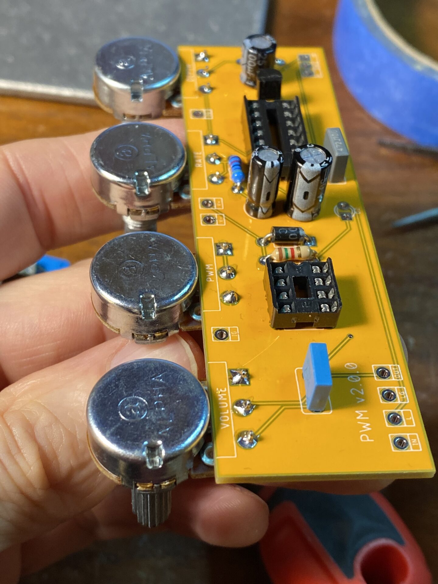
I didn’t have any of those pots with the longer legs. I made due with some of these side mounted pots by bending the pins down. The board ended up closer to the enclosure but wasn’t shorting on the interior.
NOTE! I soldered the 14 pin DIP socket backwards! The notch is on the wrong side in this images. The PCB is correct.


I bought some of these stomp switches with built in LEDs. These have a really large threaded body and a four LEDs shine up through grooves in the side. They work fine but I’m not sure I like the look. This project seems to be giving me an outlet for parts that were clogging up my parts bin.


I tried to make a smaller version of this board to fit a 1590B box. But it didn’t workout. I took a second try and did this version for a 1590BB sized enclosure. This worked out pretty well. I think the overall design works well with the two foot switches and the larger “flying saucer” knobs.
Build your own PWM!
This board is meant to fit a 1590BB sized enclosure in landscape orientation. Use this drill guide. Be sure to download and print this at 100%.

Partlist
| Part Number | Value |
| Capacitors | |
| C1 | 47µ |
| C2 | 2µ2 |
| C3 | 100µ |
| C4 | 5n |
| C5 | 100n |
| Diodes | |
| D1 | 1n5817 |
| D2 | LED |
| ICs | |
| IC1 | 40106 |
| IC2 | LM386 |
| Transistors | |
| Q1 | 2N3904 |
| Resistors | |
| R1 | 33K |
| R2 | 47K |
| R3 | RLED |
| Potentiometers | |
| DEPTH | B10K |
| PWM | B500K |
| RATE | B500K |
| VOLUME | A100K |
Schematic for reference

Wiring diagram
The bypass LED and resistor is mounted to the board. To add an LED for the modulation switch use one of the poles on that switch.


Leave a Reply