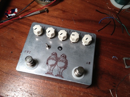
The Echobase is a PT2399 based delay with some extra features. It was developed as a DIY project at diystompboxes.com.
*** by who! post a link
The effect includes an LFO that varies the delay time. At low depth the effect adds some subtle vibrato. At higher depth the echo has strong vibrato to wildly out of tune. The effect is very nice at subtle settings and adds a lot to straight delay. While the higher settings create some pretty extreme sounds.
The PCB includes pads to add an LFO switch. The switch turns the LFO on and off. Without the switch the LFO is always on. In this mode turning depth down removes the effect of the LFO. This makes the switch not strictly necessary. I opted to use a foot switch for the LFO. My reasoning was at extreme LFO settings it be nice to be able to turn the LFO on for a moment, and then off again. We’ll see how this plays out in actual use.
The effect is not true bypass. It includes an electronic switching system, which allows for a trails/tails option. In trails mode, echoes continue when the effect is bypassed. This option is switchable.
Switching is handled electronically this includes the status LED. Which by the way is tied to the LFO section. This is a nice addition, which makes the LED pulse at the speed of the LFO when the effect is engaged. Only a single throw switch is required since the bypass and status LED are handled electronically.
I got two PCBs from MusicPcb.com. These were well made and nicely laid out. The board does not fit a 1590B box, which is my favorite form factor. It does fit the 1590BB size, which actually works out well since the device has five knobs, a toggle switch, and up to two stomp switches, if you choose to include a stomp switch for the LFO.
The pots are all board mounted in a row along the top. This is great and makes for an easy build. With this layout a BB sized box must be arranged in landscape.
Since the switching is all handled by by the circuit, and the pots are board mounted there is very little off board wiring. While PCB is fairly crowded making for a moderately difficult build, the off board wiring is fairly simple.
The first board worked almost the first try, with little effort. I made a minor error in wiring on the first attempt. This was easy to trouble shoot, bingo lush, ambient, swirling delay.
When I built the second PCB, I soldered the chips to the board, expecting it would work like the first. Of course it didn’t. After some extensive debugging I decided to remove the PT2399, install a socket, and try another PT2399. Removing a 16 pin DIP is a hassle. In the end I had to sacrifice the chip. I cut all of the pins, then desoldered each pin one at a time.
After installing the socket I tried a new chip. At this point I had delay but there was a lot distortion in the delayed signal. So, I tried a third chip. With this chip everything started working as it should. All of the chips came from the same order. If I recall these were all cheap chips I ordered from Futurlec. While I like Futurlec for cheap parts I think I will not get any more PT2399s from them in the future. PT2399s from Mammoth Electronics seemed to be consistently more reliable.
For future projects I will definitely use a socket for the PT2399.


Leave a Reply