Glitchstorm is an Arduino based bytebeat synthesizer. In short this is a noise maker that generates chiptune style sounds. It’s a lot of fun to play with!
In more detail, bytebeats are music generated with software via non-linear algorithm. The sounds a lot like 8 bit chiptunes. The sounds evolve over time, and can sound like they are sequenced.
Read more about bytebeats here: https://stellartux.github.io/websynth/guide.html
Glitchstorm is an Arduino based bytebeat generator designed by spherical-sound-society on GitHub.
This post is about my take on the Glitchstorm. With my version I added a LM386 amplifier. The output from the Arduino is weak. This amplifier allows the circuit to provide a line level signal, with enough power to drive an unpowered speaker, or headphones.
Build this at Noisebidge, join the meetup!
My repository for the source code here.
Glitchstorm
So what is a bytebeat synth and what do they sound like? Here is a video demo of this project:
And another video of the first version I made a few years earlier:
And another:
The first demo is an updated version of the project that includes a sample rate control, and an LM386 output amplifier.
Breadboard Layout
If you’ve used a solder less breadboard you can build the project following the diagram below.

- This is setup to run off of USB power. Connect the Arduino with a micro USB cable.
- The LM386 runs off the +5v power output from the Nano.
- I used 9mm 100k pots for all of the controls. These have pins that fit the breadboard. You can use any pots 10k to 100k. If you use larger pots you can connect them to the breadboard with wires.
- The switches are momentary, normally open types. We want these to connect ground when pressed. The switch should be making a connecting the blue wires to ground when pressed. You can use any momentary switch here.
- The LEDs show the current program number in binary. There are 16 different programs.
- I used an 1/8″ (3.5mm) jack, which I soldered, along with some pins, to a piece of prototyping board. You can take the audio output from C3 and send it wherever works best for you!
- To record the demons I connected an 1/8″ cable from the circuit to my audio interface, and recorded on my computer with GarageBand.
Schematic

The drawing above shows the same circuit on the breadboard as a schematic view. This worked better for some people, and clarifies what is going on.
Parts List
| Arduino Nano | I used a Nano, you could use other type of Arduino for this project. I used the cheaper Chinese knock off Arduino, these cost $5 on Aliexpress. |
| 4 x 1k resistors | Current limiting resistors for LEDs |
| 2 x Monetary switches | Used to switch algorithm |
| 4 x LED | Any type of LED |
| 4 x B100K Pots | These pots control the volume, and the parameters used by the current bytebeat algorithm. I used 9mm pots with pins that can be inserted into the breadboard. You can use any type of pots and wires to connect to the breadboard. |
| 100n capacitor | Used to filter the PWM output of the Arduino. |
| 100µf capacitor | Used to AC couple the output of the LM386. Any large value will work here 10µf, 22µf, 47µf, 220µf etc. Bigger is better here. |
| LM386 | Get the 8 pin DIP version of this chip! |
| 1/8″ output jack | You can take the output is anyway you like, I used an 1/8″ jack. |
| wire | You’ll need some wires to make connections on the breadboard. |
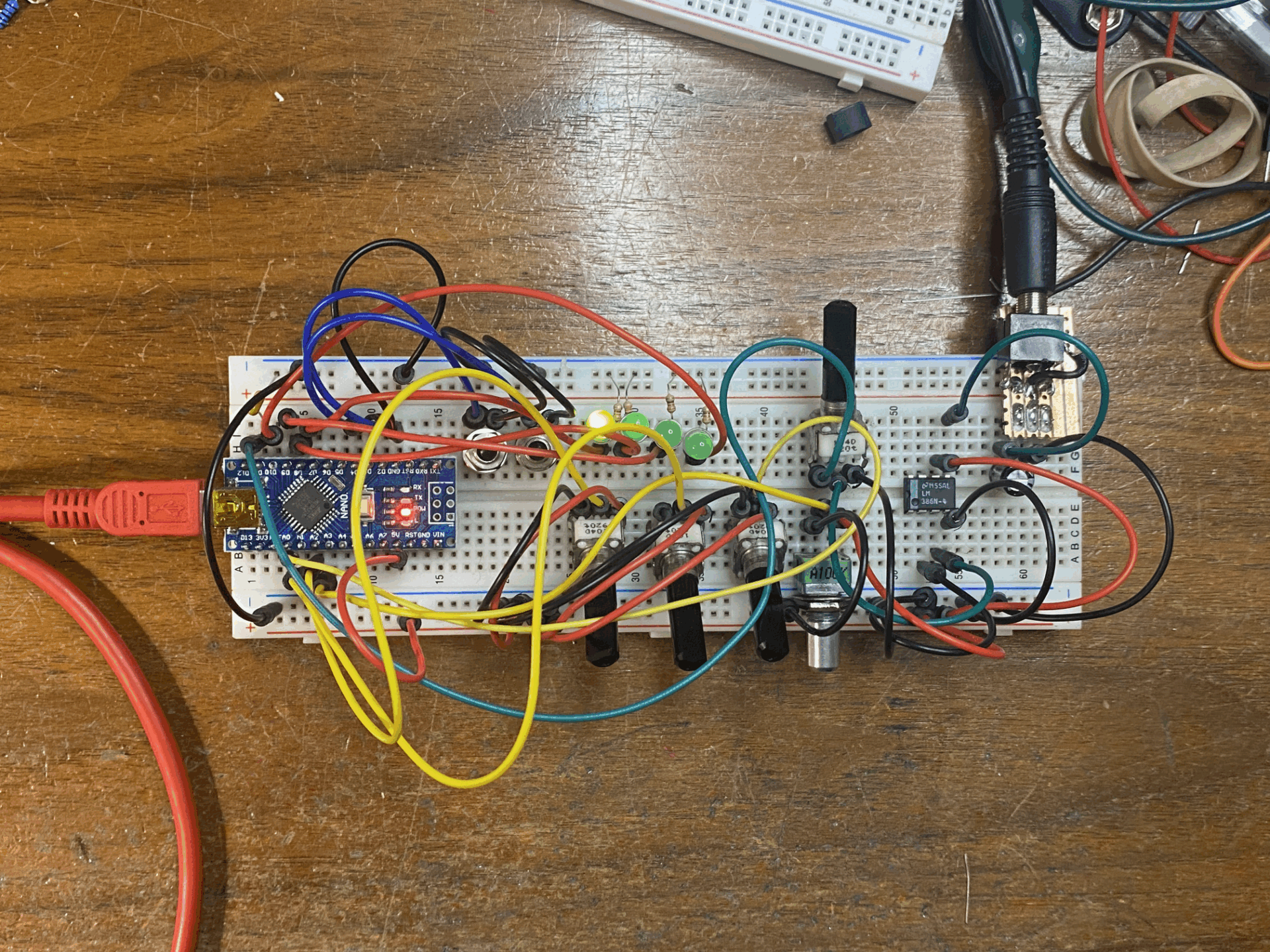
Here is a photo of my build on the breadboard:

Source Code
Here is a link to my fork of Glitchstorm from spherical-sound-society. I made a few changes.
My repository for the source code here.
Printer friendly layout and schematic PDF
Modifications
There are a lot of mods you can apply to this project. Here are a few ideas I thought of:
- Build this on a piece of prototyping board and put it in a more permanent enclosure.
- Add a power supply. The breadboard version is powered from USB. The LM386 runs on 5v. If you’re running from an external power source, the Nano runs on 6v to 20v. The LM386 runs on 4v to 12v.
- Need more output volume? As presented the LM386 in its default configuration has a gain of 20. You connect pins 1 and 8 to boost the gain to 200.
- There are too many software mods to list! Here are a few ideas:
- Investigate bytebeat formulas and install your favorites
- Add a clock input, this might drive the time counter with an interrupt
- Add one or more clock outputs.
- Add an encoder, you could use this to change programs, set the sample rate or other things.
- Add a display. This might be problematic, since the chip is using an interrupt at audio rate, the serial connection becomes unresponsive. If you can get this to work you could display the program number and other info.
- Add a DAC to output analog values, could be good for creating a CV output or something else.
- Add CV input to control the a, b, and c parameters.
Leave a Reply