This is a board I created for Deadastronaut’s Tremshifter. The Tremshifter is a combination tremolo and filter. It has two LFO’s, one for each the tremolo and filter, with a rate and a depth pot for each. The tremolo section has a shape switch for square and triangle. The filter section has a an on off switch and a filter range switch.
The effect can be a standard tremolo, with the filter off. The tremolo is a similar to the Tremulous Loon a popular DIY tremolo. Here is a schematic. Originally a DIY project from way back when, by Commonsound.
The filter section is a modulated filter. Think of it as a mild wah with the pedal automated by an LFO. It sounds a little like a mild phase shifter or vibrato but different.
Overall the effect works well and has a unique sound. I like it best with filter set subtle. The tremolo works well as a subtle but also sounds good with a fast choppy setting.


I designed this PCB in Eagle PCB and had the boards manufactured at PCBWay.com. They are cheap and easy to work with.
The Controversy
This is a DIY project and offered as a PCB from DeadastronautFX. Check out the site. There are a few interesting PCBs. The controversy is that cloned a circuit from a small company offering the PCB. Not sure if this is right or wrong. The circuit is original. It is not commercially available as a pedal, except maybe in small numbers. I have bought five PCB from Deadastronaut, I built three of these and gave some PCBs away.
I was a little disappointed with the layout of the PCBs. They work well but switches are located in an awkward spot and the pots are not mounted to the board. This leaves the PCB hanging by the edge from the three switches and the rest of the wiring is off board.
I preferred to have the PCB mounted by the pots and switches for a more secure mounting. Having the pots mounted to the board saves a lot of trouble wiring. I also mounted the LEDs to the PCB. This makes assembly a lot easier.
Design
I made the decision to place the pots, switches, and LEDs first then arrange the parts around these. The idea was to think outside the box. That is to think about the user experience of someone using the effect. The end result is the PCB has to conform this.
I placed the volume at the top left by itself. The rate and depth pots for the trem and filter are arranged vertically with rate above depth. Below these columns I placed the switches for those sections. Tremolo has the shape switch. The filter has the on/ff and the range switches.
I placed the bypass LED below the volume knob. This is probably the one thing that gives me the most concern about the design. Ideally I want this near the foot switch.
Each of the LFOs has an LED that shows the rate. I placed these below the “column” of controls for each section. This puts them closer to the footswitch. I feel this might create some confusion glancing at the pedal to see if it was on or bypassed.
My board seems to be working well with one small mistake. The layout could use a little adjustment. I missed a connection in my schematic so the PCB needs a jumper. This turned out to be an easy fix.
The switches are close to the foot switch. With tall toggles your foot has the potential of contacting them. With short shaft switches, like this one, there would not be a problem. Otherwise the switches should be moved. I think I will leave them where they are for now.


You can see the toggle switches are almost as tall as the foot switch. I used one of these taller 3PDT switches from Love My Switches. The standard blue 3PDT switch was shorter and when depressed was the same height or a little shorter than the toggles.
I think the short shaft toggle switches would work well with the regular foot switch. Something like one of these from Love My Switches. Tayda also sells these.
The Build
This build did not go perfectly but it all worked in the end. First, I milled an enclosure. But the mills job was way off. Not sure what wen wrong here but the everything seems to be offset to the upper right. I think I milled everything smaller than it should have been. I used a round file to move the holes to get everything to fit.


After getting everything together I tested and things seemed to be mostly working but the filter depth and rate pot was not functioning. I noticed the LED would cycle at a very slow speed so it was almost working.
After checking parts and the schematic closely I noticed a missing trace from IC_3 Pin 3 and the junction of R16 and Pin 1 of the Filter pot. Luckily this was was easy to fix with a short jumper.


With this jumper in place everything was working!
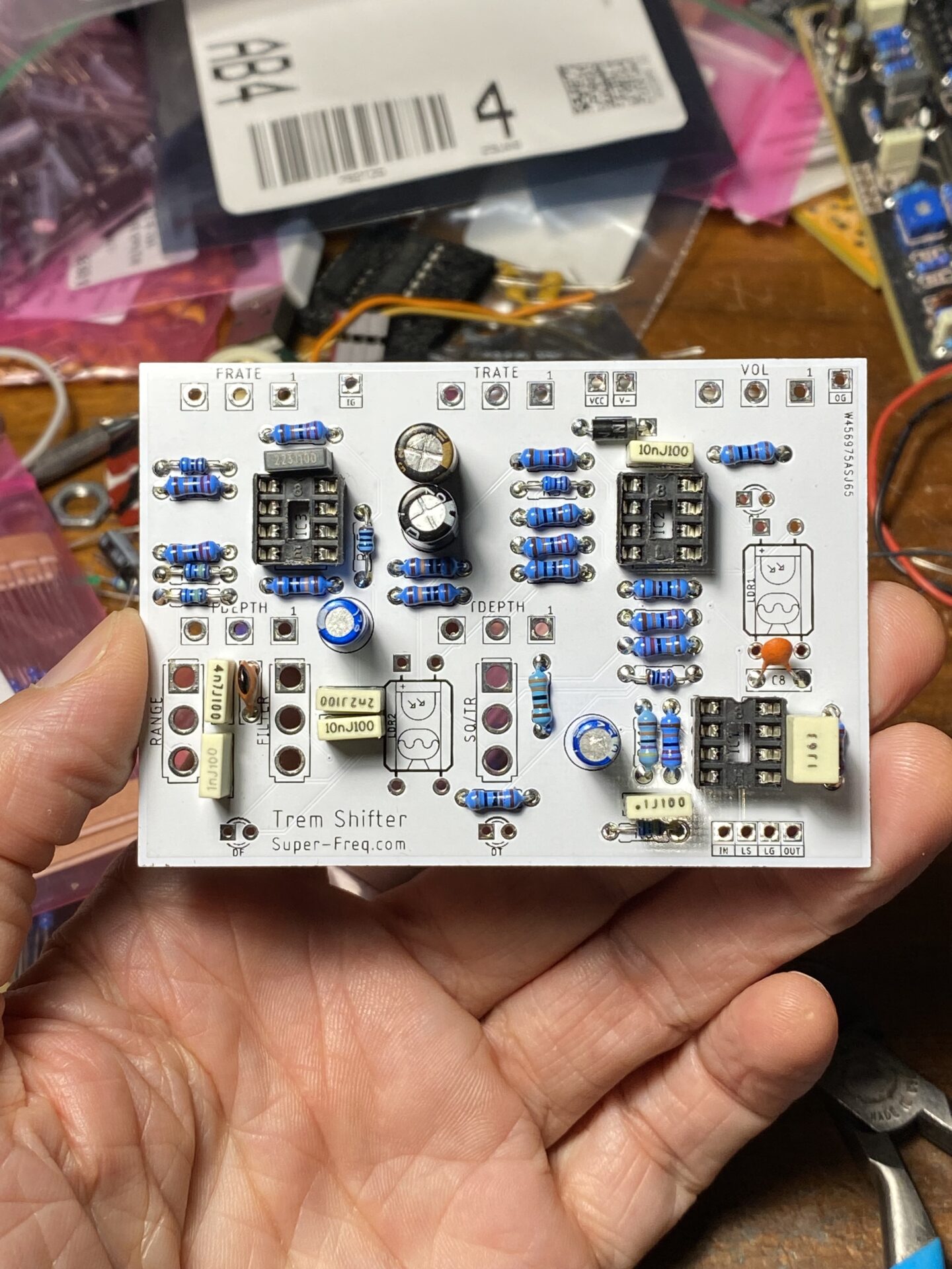
For the LED and LDR combo I used some green 5mm LEDs from Tadya and this LDR from Tayda. The LDR is described as “Photo Resistance at 10LUX: 10-20KΩ” which sounds like it matches the 10 to 20K described in the Tremshifter build docs, and only costs about $0.27, which is a lot cheaper than the VTL5C series of parts that usually run $3 to $9 each!
For op-amps I used some TL-072 types I got from Aliexpress. These may or may not be legit TL-072’s but they seem to work here. The original specs 1458 types but these are bog standard op-amps so it’s my guess that just about any op-amp would work.

Should you build this?
If you’re looking for new and interesting modulation, and prefer more sublet flavors, yeah build this. Its and easy build, requires no special parts. The tremolo is sort of your standard trem. It’s a little “soft” on the choppy mode. it sounds good and has little to no bleed.
The filter is not dramatic but noticeable. I like this for sublet modulation. Since both effects have their own LFO they will run out of sync. This adds some interesting sounds. A good future mod might be to add a switch to sync the two LFOs. With this option you might also want the option to invert the LFO.
Leave a Reply