Tag: tremolo
-
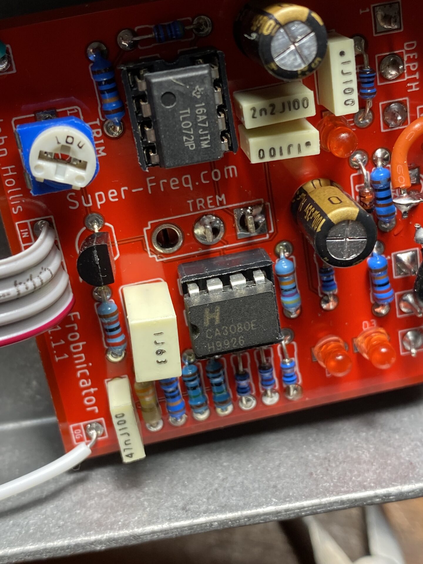
Frobnicator
This is my second try to get this right. I designed a PCB for this earlier but the errors were too great to get around. Quick overview, Frobnicator is a tremolo by John Hollis, one of the original DIY crew. He designed a few very original effects that still exist on his site. Frobinactor is…
-
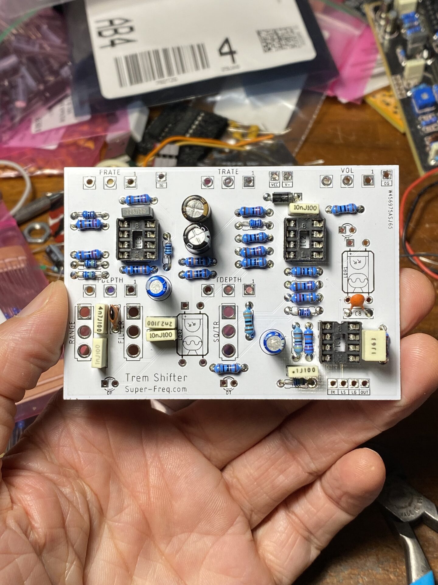
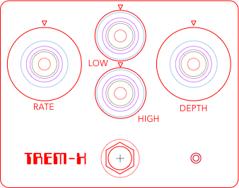
Tremshifter Build
This is a board I created for Deadastronaut’s Tremshifter. The Tremshifter is a combination tremolo and filter. It has two LFO’s, one for each the tremolo and filter, with a rate and a depth pot for each. The tremolo section has a shape switch for square and triangle. The filter section has a an on…
-
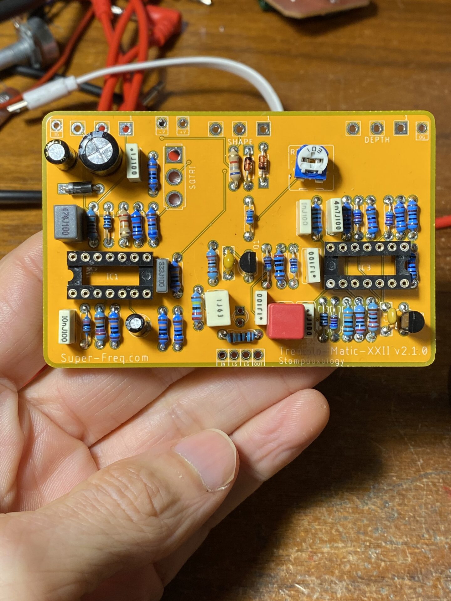
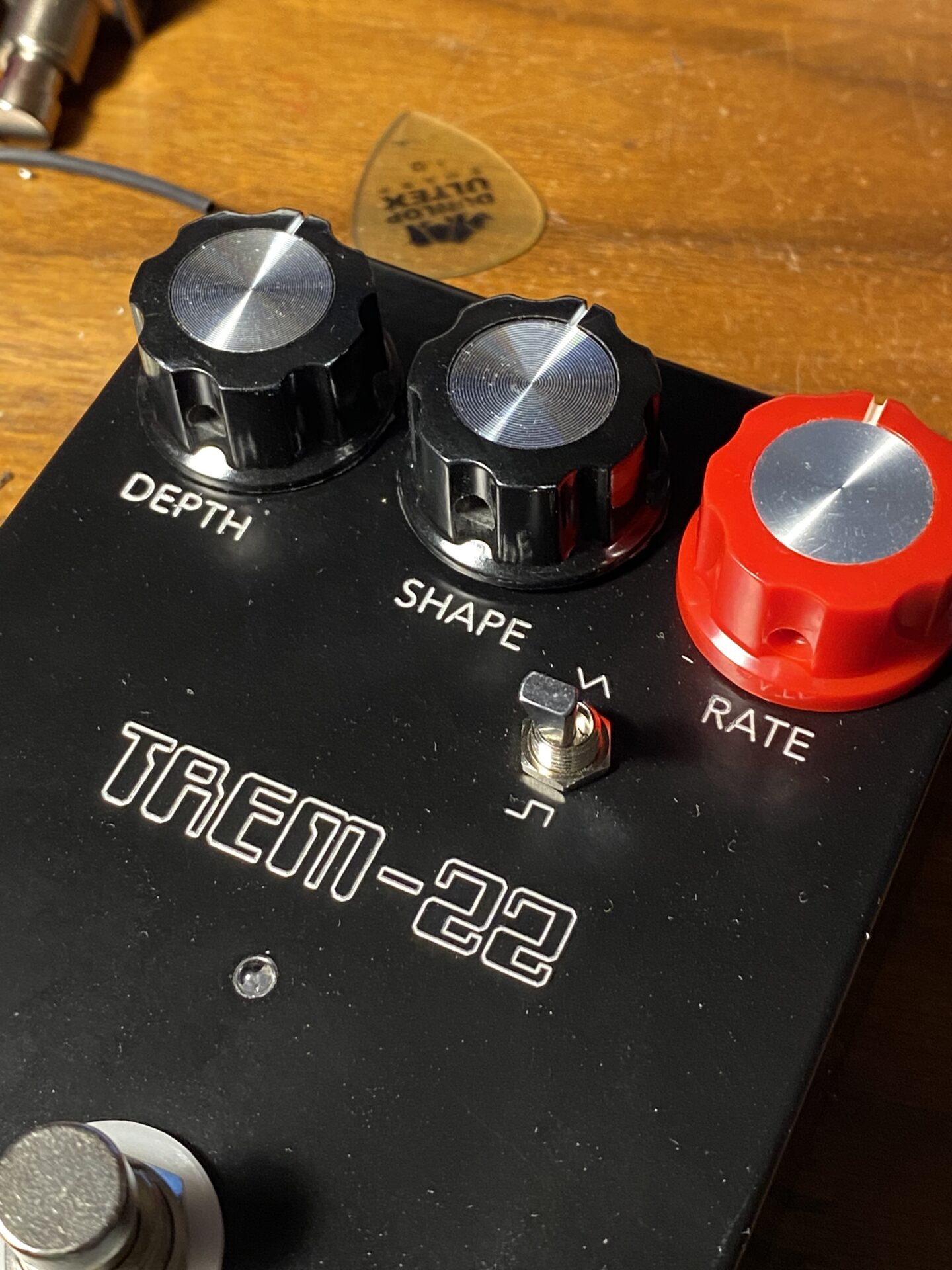
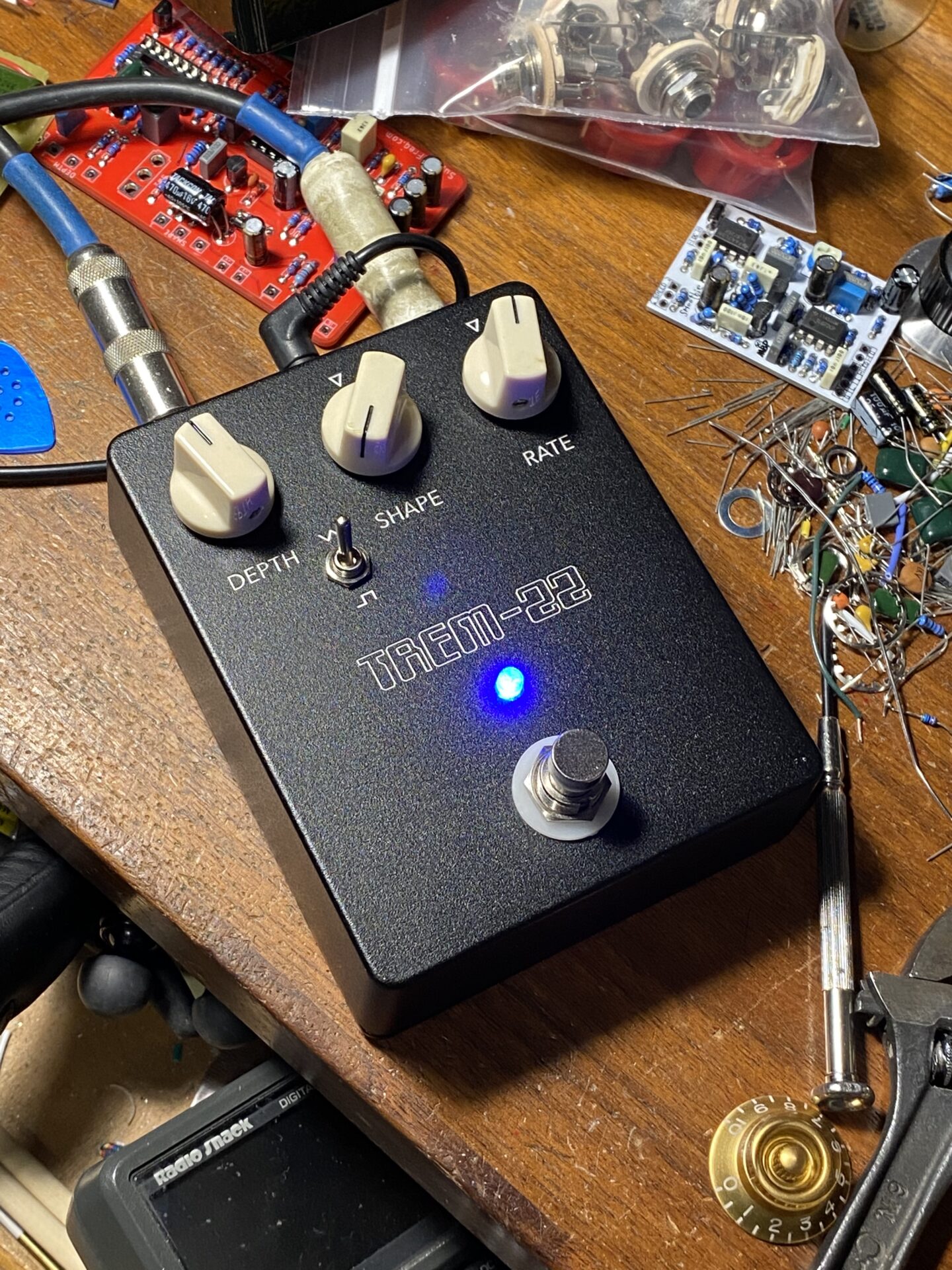
Tremolo Matic XXII Build
The Tremolo Matic XXII (Tremolo 22) is a great sounding tremolo. This is origianlly from Stompboxology. I’ve written more about it here. I made a few changes to the original design. This latest version adds a few improvements to the first couple revisions. I have been manufacturing these boards with PCBWay.com. They have a great…
-
Trem XVIII #2
A tremolo from the Stompboxoloy Newsletter. For more information and a schematic check out my previous post about the first build. I had some boards made at PCBWay.com. They prices are very reasonable. You get 10 boards for $5. That left me with a few spares. I gave a couple some friends to build. For…
-
Tremolo-Matic X build 3
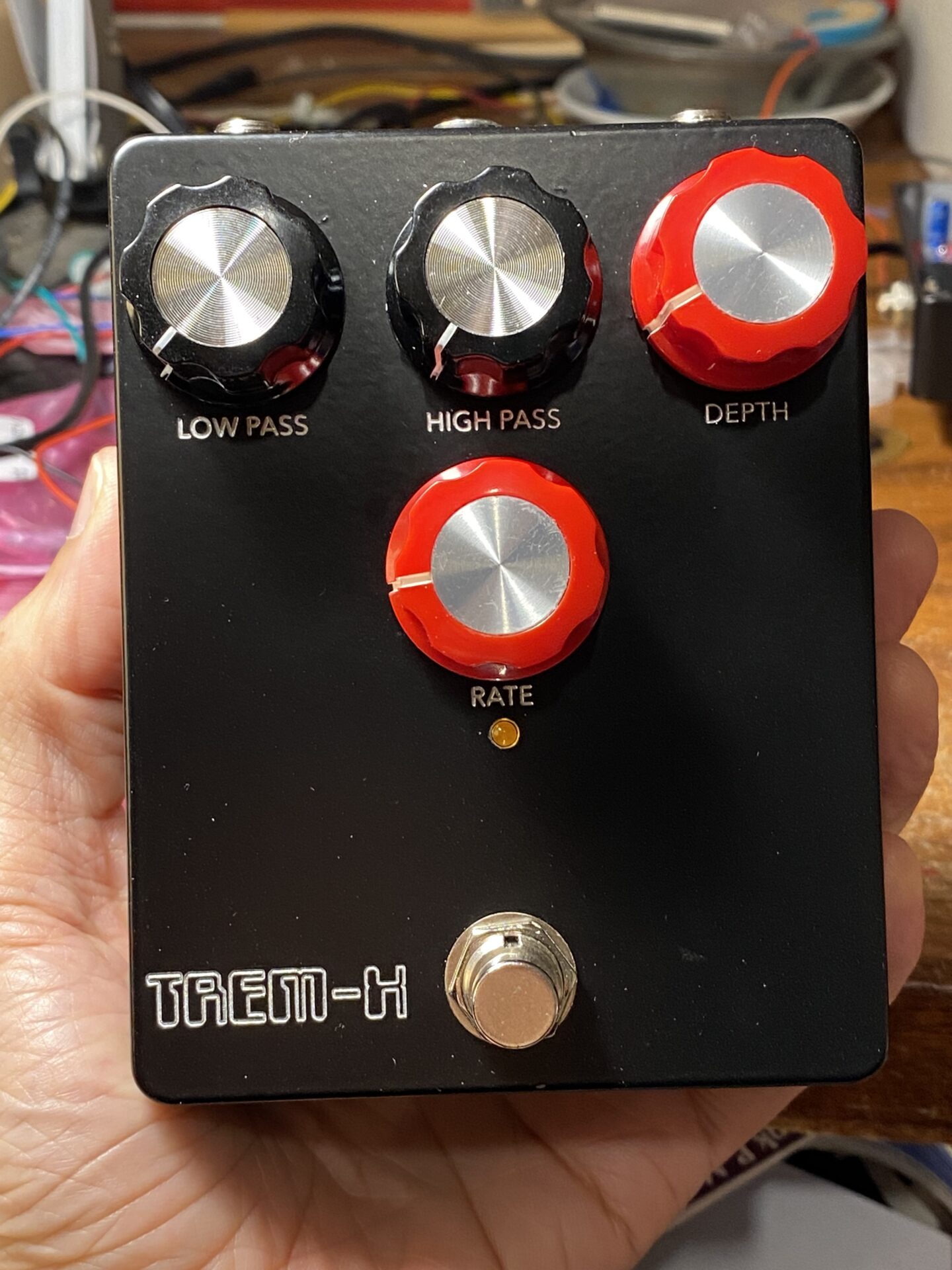
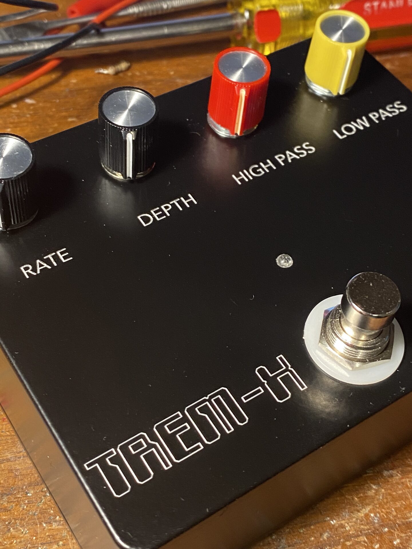
This is a new revision of the Tremolo-Matic X from Stompboxology. You can read more about it here. In a nutshell, this tremolo splits the input signal into high pass and low pass filters and pans between the two. The sound is subtle and sweet. This type of tremolo was implemented with tubes in some Fender…
-
Tremolo XXII v2.1
I updated this design again. It’s almost ready for production. In this revision, I improved the PCB layout by moving the components that make up the LFO to the left side of the board and the audio path to the right side; this meant I had to move the shape switch to the other side…
-
New PCB day!
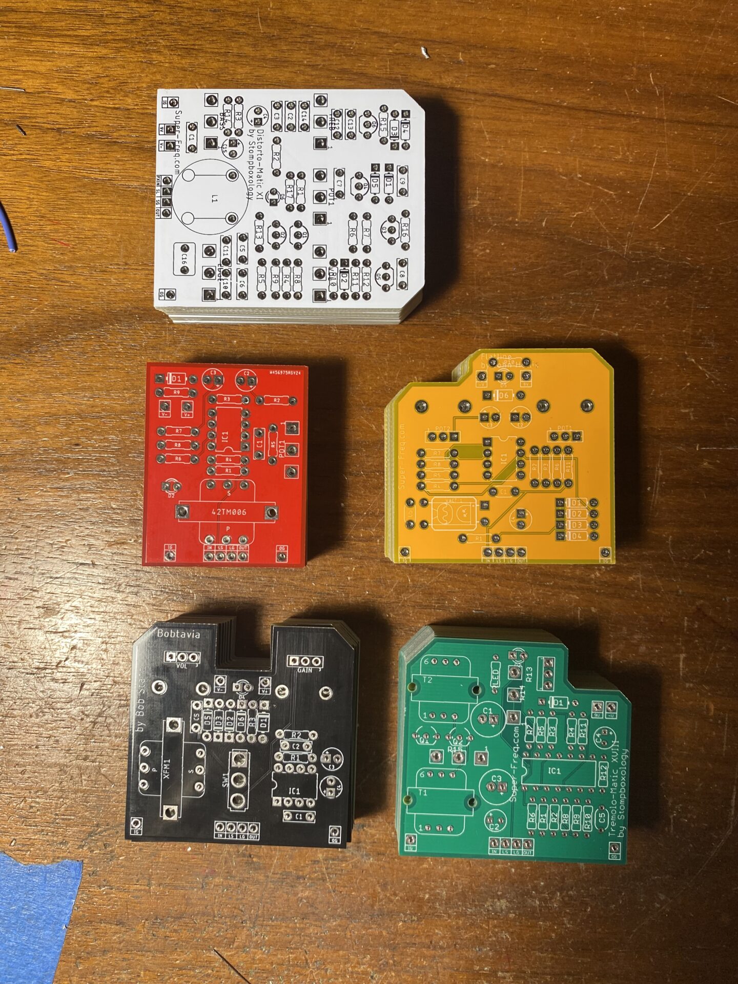
I have a few new PCB projects in the mail today. Flatline Compressor by John Hollis Titan Boost by John Hollis Tremolo-matic XXVIII from Stompboxology Distort-o-matic XI from Stompboxology Bobtavia by Bob Starr John Hollis John Hollis was one of the first people I ran into posting DIY designs on the internet. All of his…
-
Tremolo-matic X by stompboxology
This circuit is based on a type of tremolo that some Fender amp models. Its operation is very interesting. It splits the signal path into a low pass and high pass routes and alternates crossfading between each. It has a sweet subtle flavor of tremolo. I had built this circuit years ago making a PCB…
-
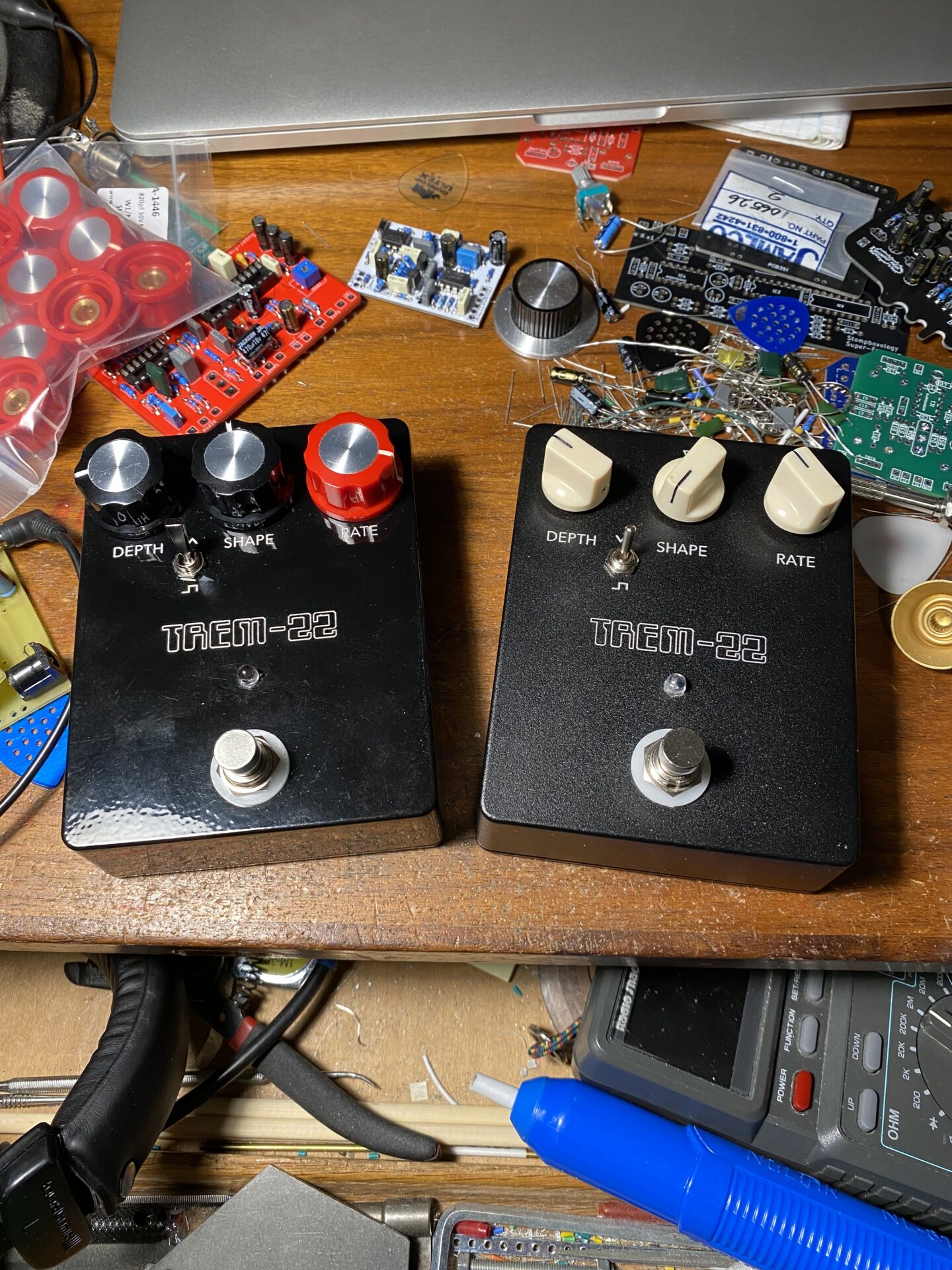
Tremolo-matic XXII v2
This project was originally from the Stompboxology newsletter. In a discussion about the circuit, the question came up about an extra op-amp used to create a second bias voltage buffer. This appears twice on the schematic as IC1B and IC2. IC2 seems redundant. I decided to test this out by making a second version of the…
-
Tremolo Matic XXII Stomboxology Update
I updated the Tremolo Matic XXII from the stompboxology newsletter by removing the single op-amp. It looked like this was used as an extra buffer for one of the reference voltages. Everything works without this extra op-amp but there is a distinct thump form the LFO. I made another run of boards via PCBWay.com. The…
-
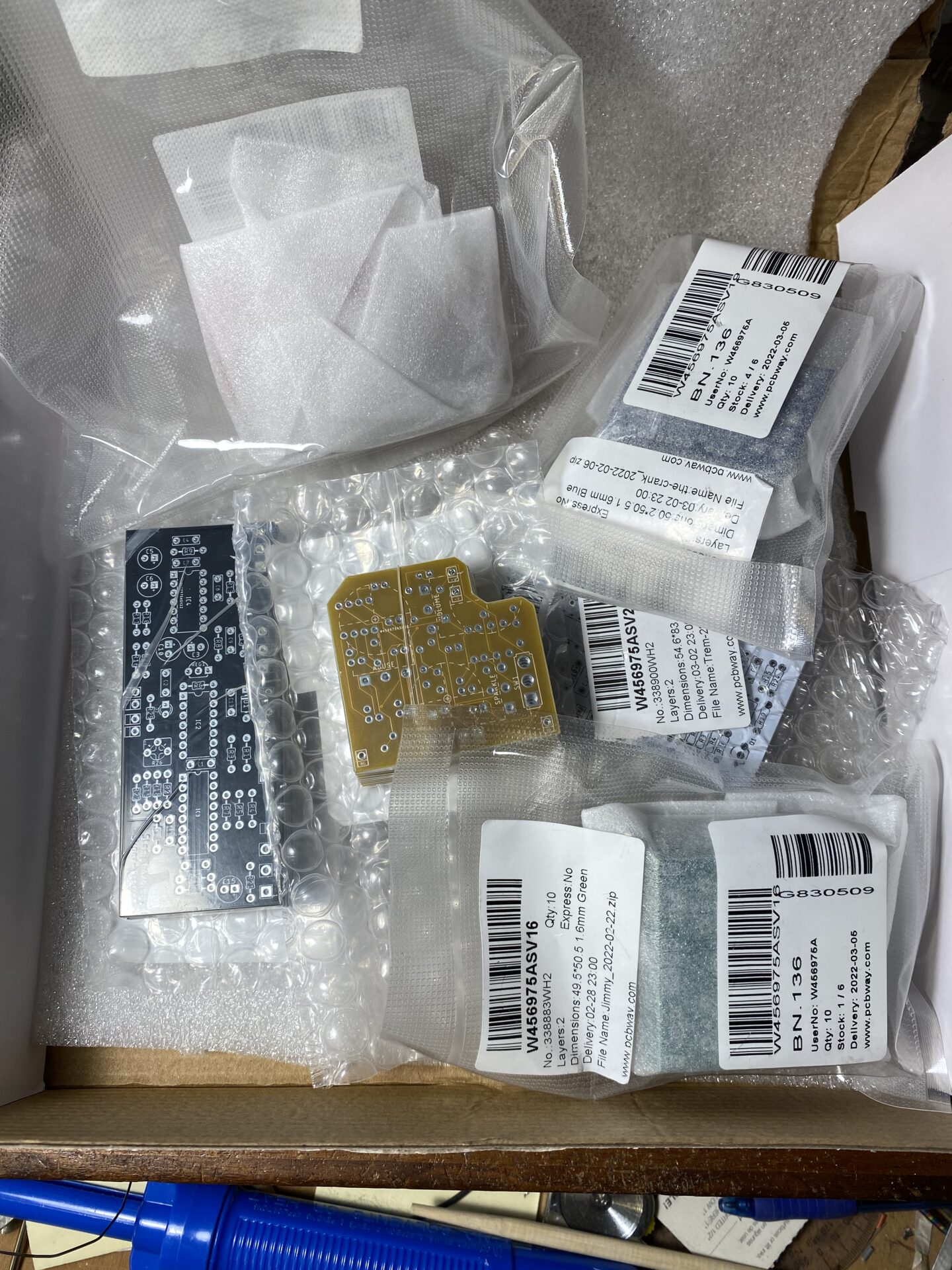
6 new PCBs from PCBWay
I got 6 new boards made at PCBWay.com. The PCBWay.com service is a great deal the biggest cost is shipping. The best deal is to order multiple boards at once since the shipping is combined. This time I waited til I had 6 boards designed and ready to go before ordering. As long as your…
-
New tremolo design
I’m working on layout for a new tremolo. Before making the PCB I’m laying out the box. This way I can design the PCB to work with this layout. This is a tremolo based on the tremolo used in some older Fender amps. The circuit divides the signal into low pass and high pass and…