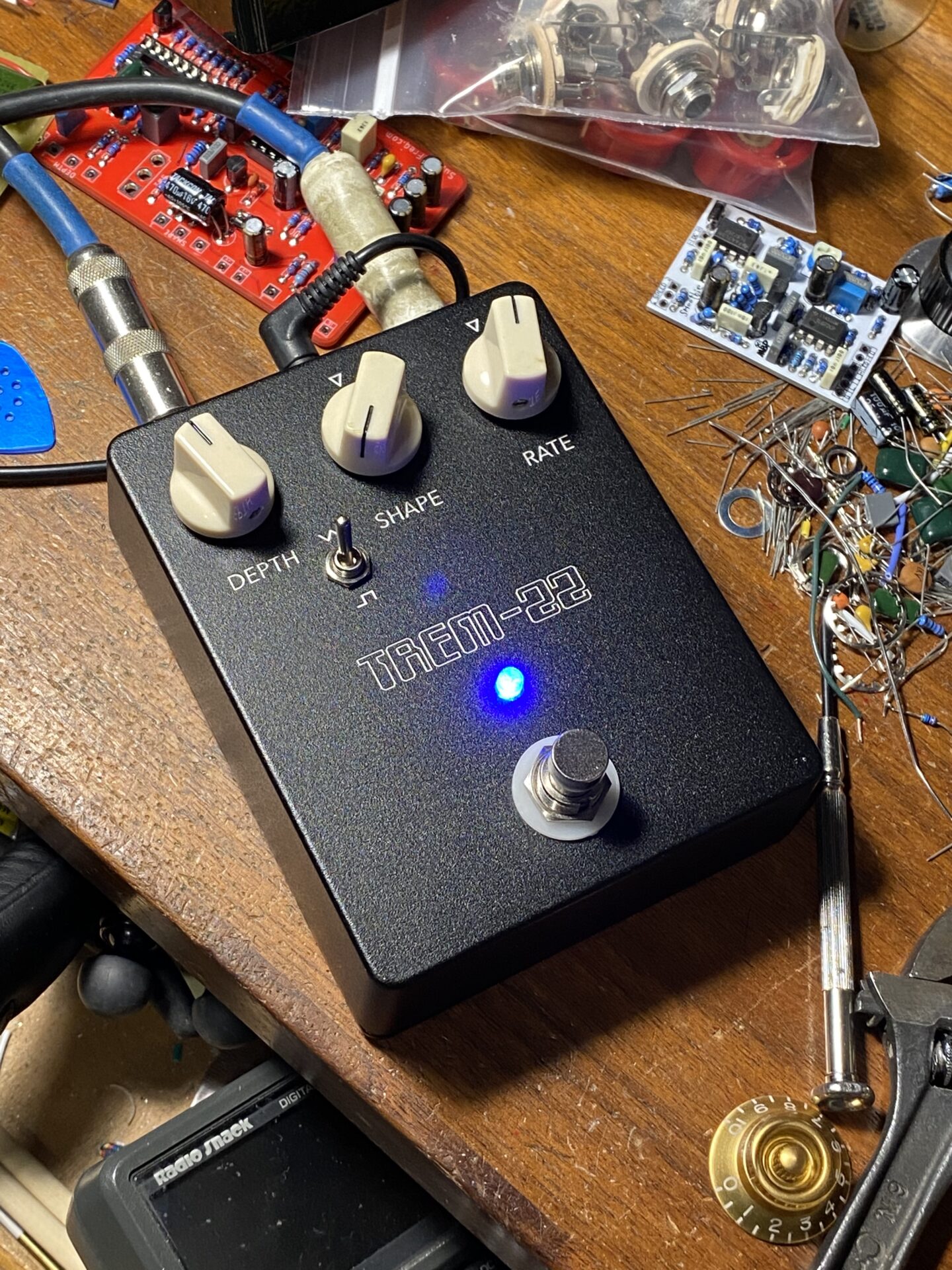
I updated the Tremolo Matic XXII from the stompboxology newsletter by removing the single op-amp. It looked like this was used as an extra buffer for one of the reference voltages. Everything works without this extra op-amp but there is a distinct thump form the LFO.
I made another run of boards via PCBWay.com. The quality is great, my design skills seem to lacking in this case. On paper it looks good but in actual use noise from the LFO is leaking into the audio path.


What changes were made
Here are two schematics to show the modification.
This schematic shows the original Tremolo-Matic-XXII by Nicolas Boscorelli.

This schematic shows the modification.

So what’s different? The power section and bias voltage in the upper left. Here’s a detail of both schematics.


IC1B outputs a bias voltage at half the power supply. In the original schematic IC2 is a single op-amp that buffers the voltage from IC1B. Why have a buffer for a buffer? IC1B should be able to supply to supply the needs of the rest of circuit by itself making IC2 not needed.
The Problem
The problem is a tick/thumping noise that happens in my modified circuit. The original doesn’t have this. Or at least any noise negligible and can be dialed out with the trim pot R33.
The only difference is IC2, R26, C13, and C14 have been removed and the LFO is and VCA are using a bias voltage from the same op-amp.
There is also some question about C14. Adding a cap like this on the output of an op-amp is not needed, bad practice even.
Probing the circuit with the scope I don’t see any artifacts from anywhere around IC1B. I do see a clear triangle at the collector of Q6.
Then there’s the trim pot R33. The parts list shows this as 5K but the schematic shows 50k. I used a 50K pot. Adjusting the trim pot starts to dial out the tick/thump. It does not dial out the sound completely. At the best setting the trim pot is dialed to 0 ohms.
Other notes
Looks like pins 12, 13, and 14 are not connected. But the notes for this chip say the substrate should be grounded?
The images below show the boards I made for each version of the circuit. I had these manufactured at PCBWay.com, keeping the size below 100mm makes the cost about $5 for 10 boards. Which makes cost of prototyping like this pretty reasonable.
Here are some pictures of a build of the modified circuit. This boards dropped the extra op-amp and attendant parts.


These pictures show the PCB I made of the original circuit. The difference is the additional single op-amp and a couple parts. This one sounds great and has very little noise.
Here are some pictures of my build of the original circuit.


Leave a Reply