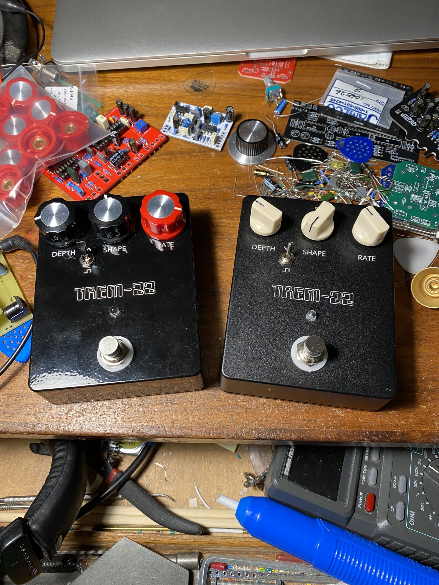
This project was originally from the Stompboxology newsletter. In a discussion about the circuit, the question came up about an extra op-amp used to create a second bias voltage buffer. This appears twice on the schematic as IC1B and IC2. IC2 seems redundant. I decided to test this out by making a second version of the board.

Here is a schematic for version 2 that drops the extra single op-amp IC2. I had an issue with the LFO feeding through the VCA with an audible thumping. I managed to remove this by changing R13 to 7.5K.

Here are the boards I made.


PCBWay.com. In the past I’ve used perf board, stripboard, and made PCBs with ferric chloride. There is a lot to learn and it’s a great hobby. That said the time, effort, and material investment is hard to compete with having the boards professionally manufactured. The quality of the boards from PCBWay is great, they are two-sided, solder masked, and pre-tinned.
Besides the quality, designing the boards in Eagle provides you with error checking and other helpful tools. Boards designed here and manufactured can have smaller traces. This allows you to fit more complex designs into a reasonable space.
My design process has evolved from trying to get all of the parts in the board connected correctly to, planning the control placement and layout of the outside of the box and making a board that works with this. Having the pots and LED mounted to the board gives My design process has evolved from trying to get all of the parts in the board connected correctly, planning the control placement and layout of the outside of the box, and making a board that works with this. Having the pots and LED mounted to the board gives you a secure place to mount the board. Fewer off-board wires make the whole thing more reliable.


Smaller traces and two-sided boards give more flexibility to place things where you want them. For example, I like the arrange the off-board connections along the bottom to make wiring the switch easy. I plan all of my boards to use the same scheme. This way I don’t have to figure out how to wire each pedal, instead, they are all wired the same!
The process of designing boards on the computer and having them manufactured has a learning curve. The workflow is different. Typically I’m spending more on the computer planning the board, no time manufacturing the boards. There is a wait for the service to produce and deliver boards. To alleviate the wait time I typically manufacture a few boards at the same time. This saves on shipping! That last point is important.
Typically the biggest cost is shipping. For example, PCBWay.com charges $5 for 10 boards under 100mm. That’s ridiculously cheap. Shipping costs are $10 to $20, ouch! By placing an order for several boards at the same time you reduce shipping by a lot. The last order I placed for 6 board designs, 10 of each, cost $30 to manufacture and $30 for shipping. That’s $1 per board. very cheap.
What to do with 10 boards? The minimum order is 5 boards but, the cost of 5 is the same as buying 10. So you should always get 10. For some reason, they always send me 11. If you’re only planning to build one pedal what to do with the extra boards?
Over years of practice, I’ve fallen into the habit of always building 2 or 3 of everything. Even when I’m making the boards myself or ordering boards from someone else. If something goes wrong with one build I can check it against the other one and compare the two. When both builds are working I can sell, trade, or gift the extra pedal. Some pedals are great to have a spare!

Leave a Reply