We’ll call this the BZ-1. What got me started on these Boss rehousings was seeing the Boss Tone Bender TB-2w going for 3k on Reverb.com. These were super cool pedals but not worth more than than the list price of $350. I understand the idea of scarcity and knew there were only 3000 made, but I wasn’t going pay even $350 for a fuzz pedal. So I figured I could make one!
The Burns Buzzaround
If you’re curious about the Burns Buzzaround and how it relates to the Tone Bender check out here articles:
- https://www.diystompboxes.com/smfforum/index.php?topic=111775.0
- https://www.tonehome.de/jmi/burns-buzzaround/
- https://www.freestompboxes.org/viewtopic.php?t=1211
Building the BZ-1
There is always a solution when you can make your own! Since it was hard to get a two knob Boss enclosure, I decided to go with a three knob Tonebender variation. There are a couple to choose from. In the end I decided to go with the Madbean Pasty Face which is a clone of the Burns Buzzaround which is variant of the three transistor Tonebender family. I had read some good reviews of the Buzzaround and hadn’t built one before which made it more attractive.
Getting started
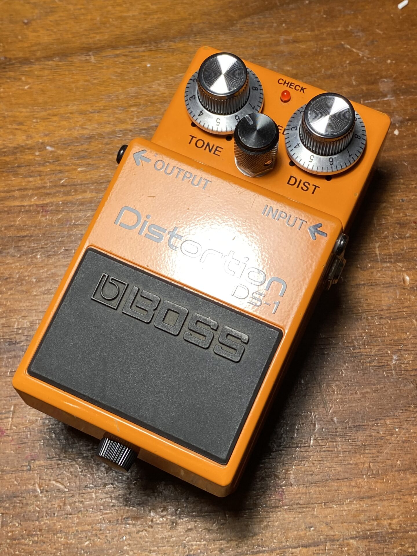
I started with a used Boss DS-1 from Reverb.com. Used these seem to go for about $40. I ordered a board from Madbean and I had most of the other parts on hand. The DS-1 comes with a lot of parts that can be reused: switch, LED, jacks, and the enclosure itself. I pulled everything out and except the jacks. I left all of the original wiring in place since I can reuse it.


The LED is mounted to a small PCB along with two wires. These wires were too short to reach the far side of the enclosure where the switching board will be so I replaced them with longer wires.


I built the Pasty Face circuit board first. I left the transistors off since these need some special selection. The build is pretty easy there are only a handful of parts and there is plenty of space to work.
Since I’m putting this into a Boss enclosure the pots will be mounted off board. I cut a piece of strip board to mount the pots to. This was tight fit using 16mm pots but just makes it. Then I soldered some strips of ribbon cable to the this board and then to the main PCB. I made the ribbon cable a generous length since to allow me to pull the PCB out without having to also remove the pots.


Boss uses an electronic switching and the enclosure is nice the way it is. I wanted the switching to work as it was without adding a 3PDT switch. To do this I used a MadBean Softie PCB. This is a relay switching system that works with a Microcontroller. The microcontroller is triggered by the original Boss SPST switch. The relay is a DPDT that handles true bypass switching, while the microcontroller handles the LED.
This system works pretty well and offers a couple advantages. The relay has a failure rate of 100k cycles which beats the 30k cycles of those blue 3PDT switches. Also, if power is lost, the relay switches to bypass. Overall I’d say this relay switching works well and is easy to install. The downside would that the cost is higher than the mechanical switch, and the parts are harder to get, I had to order relays from Mouser.com.
Choosing Transistors
The circuit uses three germanium transistors. With these old circuits there was a lot of variation with some Devices sounding better than others. I found this great thread with some suggestions about the gain and leakage for each of the transistors:
https://www.diystompboxes.com/smfforum/index.php?topic=98022.0
All pedal questions seem to lead to answers at DIYStompboxes.com. Great site and community, I highly recommend you check it out.

I have bag of germanium transistors. I got these from eBay and other sources and have been pulling parts from it for a while. What’s left are parts with less desirable values at this point. Luckily the thread above recommends lower gain devices for Q1 and Q2 and I have plenty of these!
In this circuit the first two transistors are setup in a Darlington pair. You can think of the two together as a single transistor with an hfe that is the product of the two. For example if both transistors had an hfe of 10 the pair in this configuration would act like a transistor an hfe of 100. This also multiplies the leakage of the two transistors. Which can increase noise.
Seems like the best choice here is low leakage, and low hfe/gain. Two transistors with an hfe of 50 would be considered low gain but in this configuration as a pair they would have gain of 2500!
Q3 seems like where all of the distortion/fuzz magic happens. From what I read in the thread above a higher gain, hfe 100+, is better here.
I identified three transistors that I thought would be suitable. I soldered some sockets into the board and auditioned the transistors with the back of the box open.


Everything was sounding pretty fuzzy good, so I removed the sockets and soldered the transistors to the board. I left about an inch of leg since I’d need to bend them over to fit everything into the enclosure with the back on. I wrapped the legs and the transistor body (not shown) in heat shrink tubing to make sure nothing shorted when I closed up the box.


What’s it sound like?
Sounds a lot like all those other 60s fuzz pedals but with its own character. The sound is thick and fuzzy. The tone control has a useful range. The sustain control goes from a muffled to tight buzz. Sort of like fuzzy bumblebee to swarm of wasps.
Leave a Reply to DS-1 Robert Keeley mods – Super-Freq Cancel reply