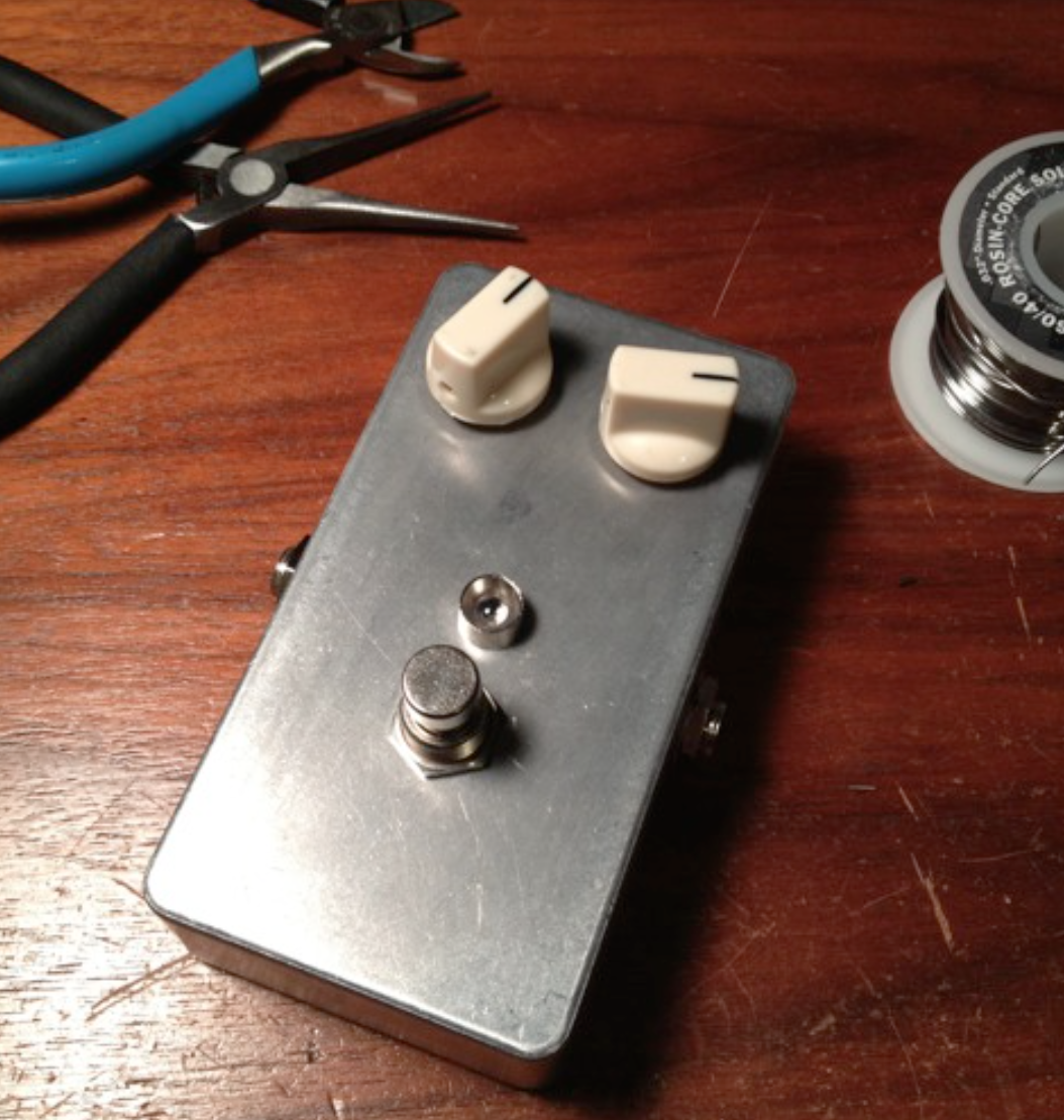
Build a Fuzz Face

This is a guide to building a Fuzz Face. It’s a step by step set of instructions. The build uses perfboard and mounts the pots on the board which makes a for a clean build with little board wiring. This is a great sounding project the parts are pretty easy to get.

Fuzz Face Build

Big thanks to my pal Joe who proof read and edited. He writes a really good blog you should check it out: http://tonefiend.com

Screen Shot 2017-02-25 at 10.01.29 PM Screen Shot 2017-02-25 at 10.01.46 PM


Posted

in

by

Comments

5 responses to “Build a Fuzz Face”

  1. Daniel kalfa Avatar
    Daniel kalfa

    hey there,
    I’m building the fuzz face by Mitchell Hudson, this is my first build, and I start working on it, I’ve ordered all the parts, but i have one part that I’m not sure about it. in the Docs it’s pointing to get 2n3904 transistors, but it says also to use PNP, I’ve got the 2n3904 and it’s NPN, and all the places i’ve searched says that 2n3904 is NPN, so I’m not sure which part I need and if I have the right part, I will be greatefull for help with that.
    thanks in advance.

    1. admin Avatar
      admin

      Great question. You can use NPN transistors. The original used PNP types but it also used a reverse power supply. If you switch the + and – on the power supple and point the – leg of the any polarized caps to ground you can use NPN type transistors. The added bonus is these transistors sound good, are easy to get and work with a regular power supple so you won’t need to power it with a battery.

      1. Daniel kalfa Avatar
        Daniel kalfa

        Thank you! so the schematics as they shown, is for NPN? or do I need to change something?

        1. Daniel kalfa Avatar
          Daniel kalfa

          Sorry for all my questions, I’m new to that and I don’t know much about electronics, if I understand correctly, if I want to use NPN transistors, I need to rotate C1 and C3 180 degrees,(C2 is not polarized so iI can leave him as the original schematics show). also I need to connect the +9V to ground and -9V to positive. also by that i can connect the pedal to power supply and not necessarily use battery.

          1. admin Avatar
            admin

            I think you got it. Take a look at the schematic here: http://diy.smallbearelec.com/HowTos/BreadboardSiFF/BreadboardSiFF.htm compare it to the one in the pdf. The differences are that the battery has – going to ground and the caps are oriented with the – leg pointing too ground.

Leave a Reply

Your email address will not be published. Required fields are marked *