Here’s another project from Nicholas Boscorelli’s Stomboxology newsletter: Going Discreet. Described by the author as:
All-transistor distortion box with aggressive tone controls.
Nicholas Boscorelli
When I look at this I see a diode clipper similar to the Electra, DOD 250, MXR Distortion+, Proco Rat, and others, combined with a Super Fuzz octave Fuzz type octave fuzz, and an active tone stack.
Here is a schematic:

I have wanted to build this for years now and have finally gotten around to it! Most of the parts are easy to get, but there are a few that are harder
The input uses a J201 FET. These are getting hard to find. Here are a few possible substitutes:
- 2N5457
- 2N5458
- 2N5459
- NTE458
- 2N3819
The tone section uses a 500 mH wah inductor. Not hard to find but not easy either. Here are a couple places you might look for this:
- Pull one out of an old wah pedal
- Stompboxparts.com wah inductor $5
- Small Bear Electronics inductors
The clipping section uses a couple Germanium diodes. These are getting harder to find.
- Stompboxparts.com diodes
- Small Bear Electronics diodes
Seems like Stompboxparts.com has the better deals on these parts! They also have 2N5457 JFET.
Looking at the Circuit
Q1 is a high impedance buffer with a gain of ~1. Q2 is a gain stage that boosts the signal by about x47. From Q2 signal splits between the edge control and the Phase splitter Q3.
Q3, Q4, and Q5 form a full wave rectifier. This produces an octave fuzz and is similar to circuits found in the Super-Fuzz, Kay Fuzztone, and Third Man Bumble Buzz. The output of this section is mixed with the signal from Q2 at the Edge control.
The mixed signal from the wiper of the Edge control is clipped by D3 and D4 then onto the tone section at Q6.
The output and active tone stack is formed by Q6, C7, C6, and L1. The tone stack allows for a wide range of treble and bass boosts or cuts. This is different from most tone controls you see in Stompboxology circuits which only cut. Here the controls are neutral in the center position and boost or cut as you turn them to one extreme or the other.
I built the circuit as it appeared in the original article. On closer inspection, it seems to lack any power filtering. This will have to go into an update.
Build
I put the circuit into Eagle and generated a PCB design. Then sent these to PCBWay.com for manufacture. Prototyping with PCBWay is very reasonable at $5 for 10 boards! I was looking at their pricing and realized buying 10 is cheaper than buying 15 or more. The 10 board option must be a special price.


After getting the boards I realized that I spec’d a regular 16mm pot where I should have used a trim pot. 🤦♂️
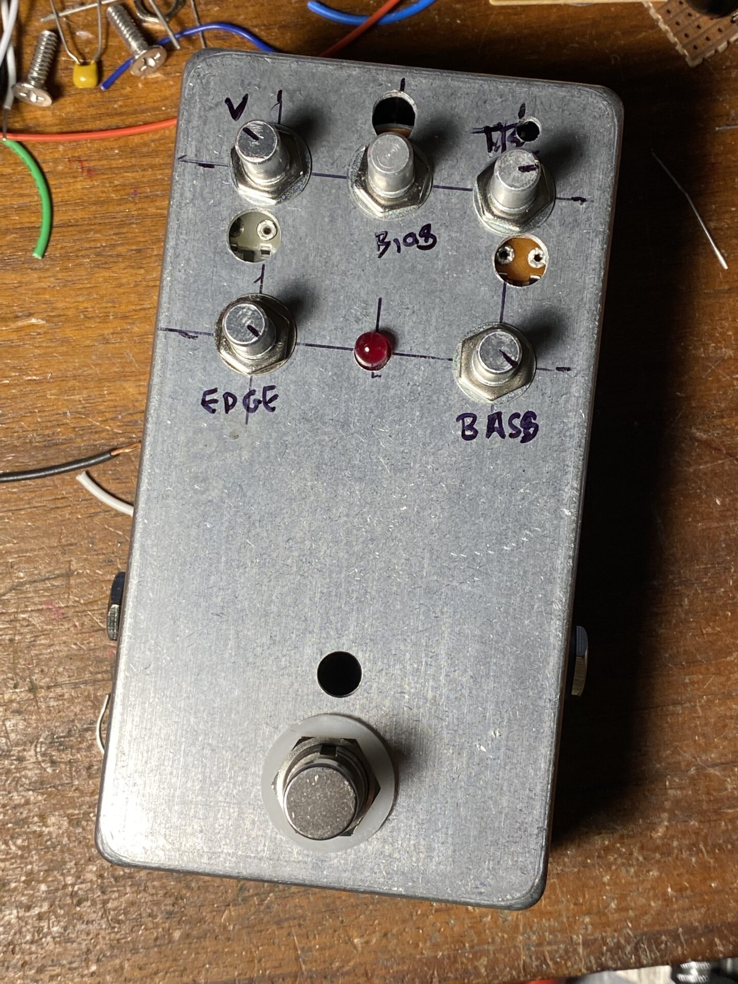
I wasn’t sure about this layout and hadn’t built the project before. I don’t remember seeing anyone else building this, so I used a scrap enclosure that had already been drilled. This is definitely a prototype!


I pulled an inductor out of an old wah PCB I had in my parts bin. The pins were not the same spacing as the footprint on the PCB. So I mounted this on a small piece of perf board with some wires coming off.
I have a couple of the Fasel inductors from Small Bear Electronics. The pin spacing on these also did not fit the footprint on the PCB!


I used a socket for the J201. It’s a prototype I might want to pull this out later.
Speaking of that JFET, the bias pot needs to be adjusted to get 4.5 v at the collector of Q2. “Conveniently” I had made this an external control so the adjustment was easy.
What’s it sound like?
Sounds pretty good. Mine had some noise. This could be due to the lack of power supply filtering. This would be easy to add in an update.
The Edge control mixes in the octave fuzz with the signal from Q2, which I suspect is distorting to some extent. The octave fuzz is a pretty fuzz with a hint of an octave. The octave is not pronounced but is there in the background. The edge control adjusts the flavor of the fuzz rather than having the effect of mixing different sounds it has the effect of missing two different fuzz tones.
The tone controls have a wider range than most. The boost and cut are nice. The bass control adds a wider range of tones.
Conclusion?
Definitely worth building. I think I will follow this up with some fixes to the PCB.


Leave a Reply to Distort-o-Matic XI demo – Super-Freq Cancel reply