This is my spin on Tim Escobedo’s Ugly Face. The original is a great DIY project anyone that hasn’t built it should give it a try. Super fun, unique sound, parts are easy to get, and it’s not a difficult built. This version makes a few changes to the original.

The original uses an LM386 as an input amplifier. Pins 1 and 8 are connected creating an amp with a gain of 200. There is nothing special here since the sound is all generated by the 555, the LM386 has little effect on the sound a the output.
I replaced the 386 with a dual op-amp. You can use any dual op-amp. I setup one half of the op-amp with a gain of 200. The LM386 in the original is configured with a gain of 200.
With the second half of the dual op-amp I created a mixing amplifier. This mixes the output the first op-amp with the output of the 555. This allows you to mix your clean signal with the distorted sound to get a wider range of sounds and add some dynamic.
After building this I’m realizing the gain on the first op-amp could be adjusted. Maybe some clipping diodes would be good there also. With a gain of 200 the first stage clips with hard op-amp clipping so the clean signal is not exactly clean.
Adjusting the gain would be as easy as adjusting R11. In the schematic above the gain is x 201 or 1 + (R12 / R11). Not sure what the optimal value might be here. I’ll have to experiment.
After some testing it seems like the gain of the first stage needs to be high, around x200, to get the envelope to work correctly.

| Part Number | Value |
| R1 | 1M (pull down to prevent switch popping) |
| R2 | 480r |
| R3 | 100k |
| R4 | 56k |
| R5 | 1k |
| R6 | 47k |
| R7 | 2k (LED resistor) |
| R8 | 10k |
| R9 | 10k |
| R10 | 1M |
| R11 | 200k |
| R12 | 1k |
| D1 | LED |
| D2 | 1n5817 |
| C1 | 220n |
| C2 | 1n |
| C3 | 10n |
| C4 | 100n |
| C5 | 100n |
| C6 | 470n |
| C7 | 100n |
| C8 | 220p |
| C10 | 100n |
| C11 | 100µ |
| C12 | 47µ |
| C13 | 100µ |
| C14 | 2µ2 |
| C15 | 10µ |
| VACT | Any LED/LDR pair |
| ENVELOPE | B1k |
| FREQUENCY | C100k |
| THRESH | B10k |
| MIX | B10K |
| VOL | A100k |
| IC1 | TL072 (or any dual op-amp) |
| IC2 | 7555 (or NE555) |
This circuit should work with just about any dual op-amp.
The VACT_1A and VACT_1B can be any LED and LDR or a combined LED/LDR device. Just about any parts should work here.
The 555 timer should be a CMOS device like 7555 or NE555.


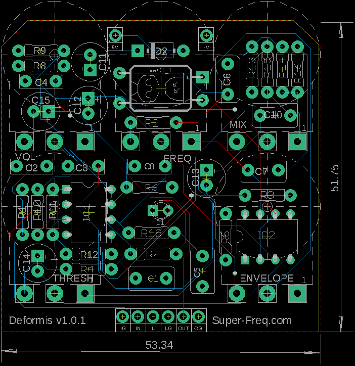
I Designed the circuit in Eagle PCB and then designed a PCB to fit a 1590B. I had these boards manufactured through PCBWay.com. They always do great work.
In the first version of the board I had missed the connection from the junction of VACT_1B, R2, and C6 to IC2 pin 2 and 6. Everything appeared to be working but the the frequency pot and envelope was not working. I was able to add a jumper on the back to fix this.
Here is a link to a drill guide! Be sure to print this at 100%. Check the 1″ square in the lower left corner.
Leave a Reply