The Flatline is a compressor with a simple effective design. It works surprisingly well for its simplicity. I’ve built a few of these over the years on strip board. This time I decided to make my own printed circuit boards.

Who is John Hollis?
John Hollis was an early contributor to the DIY Pedal scene. His designs are very solid, original, and innovative. All the pedal designs have been built successfully by the DIY community for years. Check out his site, there are some great ideas there.
What is Flatline?
The Flatline is an optical compressor. It uses an LED/LDR combo or Vactrol. The circuit itself is not picky about the parts you use. What I mean by that is that you can use any dual op-amp, any diodes, and any LED and LDR and it will work. You won’t have to worry about sourcing hard-to-find or expensive parts. The choice of LED/LDR/Vactrol will affect the attack and release times of the effect but, the circuit should work with just about any variety of these parts.
Another great thing about Flatline is that it’s been around long enough that people have built, written about, and modded it, and there is a lot of good information available.
- https://sites.google.com/site/flofxdiy/flatline-compressor
- https://www.diystompboxes.com/smfforum/index.php?topic=113163.0
- https://www.youtube.com/watch?v=gsQAcSQ2USw
- https://stompville.co.uk/?p=50
- https://www.tumblr.com/blog/view/atomiumamps/158891400886
You can find more with a search. These were articles that I found useful.
What’s a compressor?
Ovnilab.com has reviewed hundreds of compressors, check them out here. Madbeanpedals.com has a version of the Flatline called Afterlife. Ovnilabs did a review of the Afterlife here.
it’s a strong contender for “best micro compressor”
Ovnilabs.com
Want to learn more about compressors? Be sure to check out Ovnilabs: What is a compressor and how do you use it?
Design Process
I created the project using Autocad Eagle PCB. I entered the schematic from John Hollis web site. I drew the outline of the PCB to fit a 1590B enclosure. Then I placed the pots and LED. I left a notch in the upper left to leave room for the power jack.
Next, I placed all of the off-board connections. I spaced the four connections in the center at 0.1″ to work with these ribbon cables. Using the ribbon cable saves a lot of time assembling, and prevents errors in wiring.
I ordered the connection: IN, LED, GND, OUT. This makes the wiring compatible with these 3PDT PCBs, which saves time on wiring.
With these in place I arranged the rest of the components on the board.
I sent the boards out to be manufactured at PCBWay.com. They have been my go to for PCBs. Their website is easy to use and and the the prices are very reasonable. Manufacture and shipping times for this project was were quick, about 3 days for manufacture and a week for shipping. Thanks PCBWay!


Building Flatline
I assembled the board by first placing the resistors and working my through the parts in order of size, standard procedure.
Diodes
The circuit works with almost any diode. I used some fake 1n34a types. I had a bag of these that needed to be used. This was the first build for this board so I didn’t want to use “mojo” parts until I confirmed the PCB was problem-free.
LED/LDR
The circuit is not too picky about the LED/LDR, almost anything will work. I said “almost” because I haven’t tried everything. From what I’ve read, the internet seems to think that all of the commonly available parts work well, and any LED and LDR from your parts bin will work.
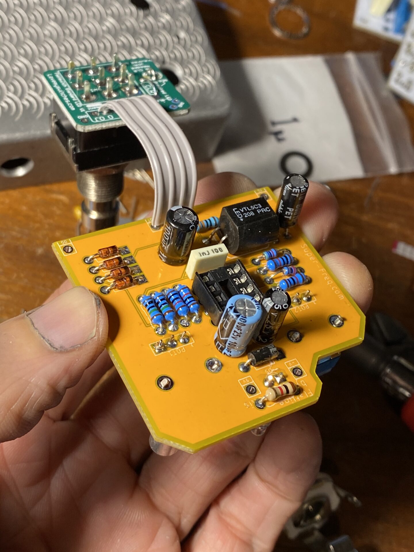
I used a VTL5C3 because I had a used one that needed a new home.
Op-amp
Again the circuit is not too picky. Since all dual op-amps have the same pin arrangement it’s easy to swap these if you install a socket. You could try them all!
All of the usually suspects work here with subtle differences. Popular choices are:
- TL072
- 4558
- 1458
- TL082
- NE5532
The Enclosure
I was experimenting with milling patterns and chose one of these experiments to house this project. I drilled the box and installed the pots, LED, and PCB. The soldered all of these.
I disassembled everything and soldered a ribbon cable to the board and then soldered the 3PDT PCB to the other end of the ribbon cable. Using he ribbon cable like this makes for an easy trouble free build.
I put everything back in the box and soldered the 3PDT PCB to the Switch. I took everything out of the box for this picture. IT’s easiest to solder the ribbon cable outside the box and solder the switch inside the box.


How Does it sound?
Worked first try, love it when that happens! The sound isn’t dramatic but that’s the nature of compression. People say it’s working best when you don’t hear it!
This board will need an update. I forgot the name and credit on the silkscreen and one of the caps has the wrong footprint.


Leave a Reply to Flatline OP2134 – Super-Freq Cancel reply