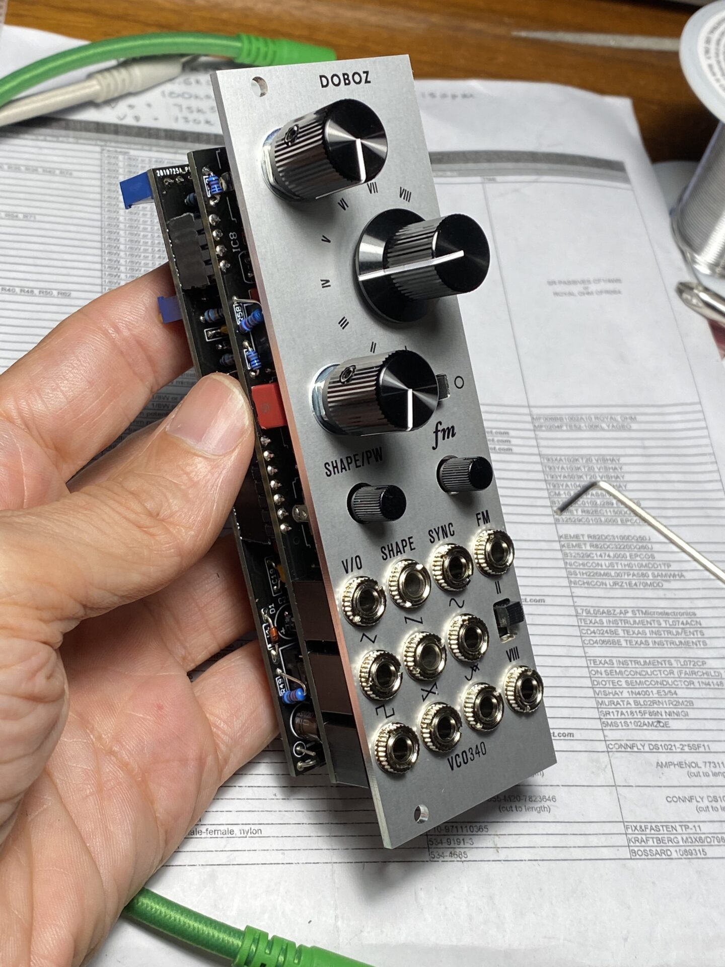
I built a pair of Doboz VCO340 VCOs. These are based around the CEM3340 chip, which was used in Yamaha DX7, Prophet and other famous synths from the 80s. Here are my notes for the build for anyone interested in building these VCOs for themselves.
The project comes as two PCBs and an aluminum front panel. The quality is very good. All of the parts are through hole. The resistors are all smaller 1/8 watt size.


Sourcing parts
Parts are not hard to get for this. There are some specialized parts that are needed. Almost everything can be ordered from Mouser.com. At the time I was building “supply chain” issues left Mouser out of stock for a few parts which made sourcing more of a hassle than it should have been.
The hardest parts to find, surprisingly, were the 0.1% 15ppm resistors. These are used for temperature stability and tuning accuracy. You could get by with regular 1% metal film resistors but tuning might drift with temperature and the octave switch might be less accurate.
You can get 0.1% resistors at:
Turns out the CEM3340 chips are readily available and easy to get these days. I expected these to be harder to find, since they had gone out of production. Now days they are back in production. You also have your choice of several manufacturers.
I opted for the AS3340. These were cheaper. I couldn’t find that there would be any noticeable difference. Some articles I researched said there was a small difference in the PWM sound. I doubted I would notice.
You can get 3340 chips at:
- ElectricDruid.net has a few 3340 options (I order here)
- Thonk.co.uk CEM3340
The original specs some Buchla style Rogan knobs. I chose to go with some similar aluminum knobs.
- LoveMySwitches.com (the aluminum knobs I used)
- Thonk.co.uk Rogan Knobs
- AmplifiedParts.com Rogan Knobs


Build
The build is not hard but, there are two boards with a lot of parts in a tight space. Luckily, parts are numbered well. One board starts numbering all parts from the top and the second board pickup the numbering and continues to the bottom. This makes it easy to locate a part by number.
Start with resistors. The board uses 1/8 watt sized resistors. You can use 1/4 watt resistors by bending the legs and mounting them standing up. You may have to use both sizes since it might be hard to get all of the resistors values in the same format.
Next diodes. There are only a few of these.
I built two VCOs at the same time. Here’s where I was with the resistors I had on hand. I had to wait while some values were on order.

I do the sockets next. These are next in height. They are shorter than the caps and transistors.
Next add the caps. C8 is listed as 1n5 styrene or C0G. The BOM shows a part number for a WIMA 10% film capacitor. I’m guessing this cap should have a tight tolerance but styrene caps are hard to find. If you can get a styrene cap you can mount this on the back of the PCB if it doesn’t seem that there will be enough room between the two boards.
I used a WIMA film cap. I had a dozen on hand so I measured them with my meter and chose the one with the tightest tolerance.
The trimmers are next. There are two types A couple have the adjustment screw on the side. The PCB, helpfully, shows the outline for this. Make sure you get these in the right place!
At this point I added the transistors. There are just a couple of these. Check the pinout especially if you are using alternative part numbers.
I opted to use a wire in place of the ferrite beads. Ferrite beads were out of stock and I wasn’t convinced that the ferrite beads were doing anything for this circuit. Read this article and decide for yourself.
Here’s where I was at:


Next I added the pots, switches and jacks. Be sure to trim the the little alignment tab off the 9mm pots! (if your pots have these)
Add all of the pots, switches, and jacks to the PCB but don’t solder yet! Add the front panel and hand tighten all of the nuts. This is a little tedious but it’s worth it to get everything aligned correctly.
Check the alignment of everything and then solder the jacks.
Align the two small pots with the plastic shafts so their shafts are centered in the hole in the panel, then solder these. This prevents them from accidentally ending up rubbing against the hole in the panel or sticking out at a bit of an angle.
Next, solder the other pots and the 8 position switch. Take a lock at the side of the panel and try and get the PCB and the front panel parallel before soldering for some bonus points!
You want to make sure the two slide switches are centered in their slots and flush against the back face of the panel. When you turn the panel over gravity should pull them flush with the panel. Solder one pin and make sure the switch moves freely. Then solder the other two legs.


I test fit everything like this, solder the pots, switches, and jacks, then took it all apart again.
Next add the headers that link the two boards together. I cut the male and female headers to length first. Then I match and connected each of the two together. Insert the headers without soldering into the bottom board. Now add the top board. make sure everything is squared up and solder. Doing this guarantees the headers are perpendicular.
Now you can pull them apart and add the chips.
Be sure to note the notch on the socket and the notch or dot on the chip and get them aligned correctly! Double check the notch in the socket against what the PCB shows and make sure the chip is inserted matching the PCB! I’ve put the sockets in backwards before!


Almost done! If you’ve got the chips in place you can put the panel back on and tighten all of the nuts. Add the knobs and you are finished.


Testing and Tuning
These fired up on the first try! Love it when that happens. They sound great.
The next step is tuning. This is a little bit tedious but not difficult. The instructions are easy to follow. I’ll quote them here:
1 – Power up your modular, let the VCO warm up for 25
minutes.2 – Connect a well calibrated, accurate CV source (such as
a midi-to-CV converter, CV keyboard or sequencer module)
to the V/O input.3 – Connect the SAW or TRIANGLE output to the input of a
frequency counter, oscilloscope or tuner.4 – Rotate the HF track trimmer (TRIM2) fully counter-clock-
wise (until it clicks).5 – Set the OCTAVE switch to its minimum position.
6 – Adjust your CV source to output 0V and by rotating
the TUNE potentiometer tune the frequency of the VCO to
approximately 25Hz.7 – Go one octave higher (increase the output of your voltage
source by 1V), ideally the output of the VCO should be twice
the frequency measured with OV at its Volt/octave input.8 – To increase the difference between two octaves turn V/Oct
trimmer (TRIM1) clockwise, to decrease the difference turn it
counter-clockwise.9 – Repeat steps 6, 7 and 8 as many times as needed to
get the best tuning, then go one more octave up, and again
iterate the same steps while checking the difference betweenoctaves. Try to get the best tracking as possible in the range
of 25-500 Hz. Note that each time you make an adjustment
of TRIM1 the tuning of the VCO changes.10 – By increasing the voltage at V/O input go a few octaves
up to the 1000-3000 Hz range. In this range the VCO will
be tuned flat, lower than what would be expected. Turn the
HF track (TRIM2) clockwise until the frequency matches the
expected values.11 – Go back and forth between octaves while checking the
DBOZ VCO340
tuning. The modules should track well from 20 Hz to 10 kHz.
The list seems long but the process is not difficult. The tedious part is tuning for each octave. Since there are 8 octaves you find yourself repeating the process 8 times and going back to check the earlier octaves.
The steps require an accurate voltage source. If you have Mordax Data you you can use this. If not you can use Ornament and Crime, or even a keyboard or sequencer if you set it up carefully.
Then you need to also tune up the lower octaves. This is faster process.
Last you’ll set the Triangle offset and sine shape. These are easy provided you have a scope. Without a scope you can do these by ear. While the idea of perfect triangle and sine shapes seem like a requirement, I think you can ballpark these by ear and be perfectly happy.
Conclusion
These sound great. What sets this VCO apart from the other CEM340 VCO, and there are a few,
- Division 6 CEM3340 VCO
- Non Linear Circuits CEM3340 VCO
- Kassutronics CEM3340 VCO
- ElectroSmith CEM3340 VCO
- LookMum no Computer CEM3340 VCO
- 2hp CEM 3340 VCO
- HoneyEater (CEM3340 VCO)
- Frequency Central CEMOSC
I’m sure there’s more! Here is a thread on ModWiggler dedicated to the topic. I’me sure all of these are good and some have more features than others. The DOBOZ VCO340 works great, and has a solid feature set and you can build it yourself, it hits a sweet spot of the size, cost, and feature triumvirate.
Should you build this? If you’re looking for a small full featured VCO on a budget it might be a good choice, provided you can use a soldering iron and figure out how to order parts on Mouser.com, then it might be worth it.
Leave a Reply