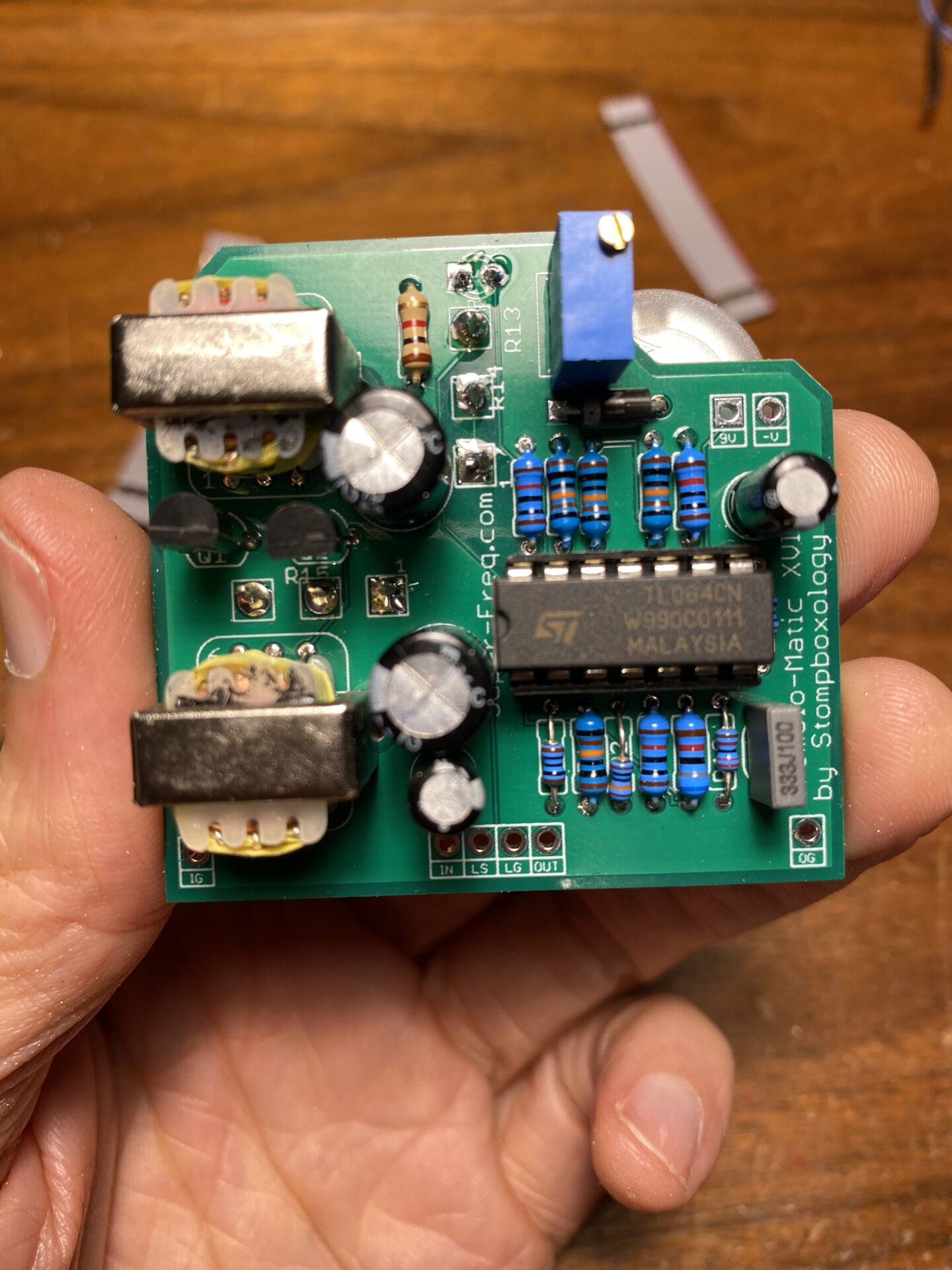
This is a tremolo built around a couple inductors, its from the Stompboxology newsletter: Going Discreet issue. If you’re not familiar, Stompboxology was a newsletter produced by Nicholas Boscorelli around 2002. It had many stompbox ideas, including circuits, layouts, and analysis. The Going Discreet issue is about building circuits with transistors. This issue has the best description of how transistors work and how to construct audio circuits with them that I have read. Go read it right now!
After writing a book (The Stompbox Cookbook) and at least 6 newsletters Nicholas Boscorelli and Guitar Project Books disappeared. A true mystery! I feel Nicholas Boscorelli missed his mark. A few years later, the interest in guitar pedals and the DIY scene exploded. If he had held on longer, I’m positive his readership would have exploded.
Here’s the schematic. Not too many transistors in this circuit, but the audio path is all transistors and inductors! The upper section, built from a quad op-amp, provides the modulation and control voltage.

Design Process
I designed these boards in Autocad Eagle PCB. Used the parts bffx-library, which had parts and footprints for the inductors! I had boards manufactured at PCBWay.com.


I planned the boards by placing the pots and off-board connections first. Then I drew the outline to fit a 1590B enclosure. I left a notch to make room for the power connector at the top of the box. At this step, I started placing the components.
The two transformers are pretty tall. I was worried they might not fit in a 1590B sized box. Before finalizing the design, I took a few measurements with the calipers. I needed to make sure height of the inductors plus the height of the board and pots would not exceed the height of the box. Everything looked good, so I continued.
I positioned the four off-board connections in the center 0.1″ apart. This makes a perfect fit for these ribbon cables. I ordered the connections left to right: IN, LED, GND, OUT. This makes the connections compatible with these little 3PDT PCB. Using the ribbon cable 3PDT board makes assembly a breeze (see the pictures below.)


I placed the inductors, transistors, and accompanying parts on the left of the board and the TL074 on the right side to separate the audio path from the modulation circuit.


Ordering boards
When the design was complete I exported and uploaded my gerber files to PCBWay.com and ordered boards. The cost was $5 for 10 boards. This a great deal, thats $0.50 per board! I highly recommend this service!
PCBWay will check your files and email if there is an issue. This doesn’t guarantee that things are electrically sound; it’s just a check that your files will manufacture correctly. Follow the guide here to export from Eagle. Use their Eagle .dru rules and Click the “Errors” button in Eagle. This will check that your board is following the rules.
Making the enclosure
I milled a box with a geometric wave pattern on the desktop mill. I used a green powder-coated enclosure.
I exported an image of the PCB from Eagle and used this to mark the holes. I drilled the enclosure. I made a 3mm hole for the LED. The LED will be mounted to the board; no need for a bezel or extra support.


First, I put the pots, LED, and PCB into the box, hand tightened the nuts, then soldered these connections. This guaranteed the pots were square to the box, and the LED was the correct height above the board.
Next, I took everything out of the box and soldered the ribbon cable and 3PDT PCB. Be sure the orientation is correct! IN on the main PCB should connect to I on the smaller board.

Next I assembled everything in the box, soldering the small PCB on to the 3PDT switch. Check the orientation of the switch! The flat side of the lugs on the switch should match the thick white lines on the PCB.
Last wire everything else. Here you are wiring the ground connections to the jacks, the power jack, and the tips of the two jacks.


NOTE! The 3PDT PCB has pads for an LED and resistor. The tremolo PCB also has connections for these. Since I mounted the LED and resistor to the main PCB, I used jumpers on the smaller PCB. You can see them in the picture above.
How does it sound?
The tremolo has a good tone, with a crisp mid-treble emphasis. The tremolo “motion” is not as nice as the Tremolo-Matic-X or Tremolo-Matic-XXII. I feel it’s not sweeping completely off, so the tremolo effect is not as deep as it could be.
The original design specs a trim pot R13. This pot shapes the control waveform. This could be useful as external control.
The design is interesting and seems to be based on a tube tremolo replacing the tubes with FET Q1 and Q2. The control voltage and modulation section make sense to me, but the audio path is a bit of a mystery. The tone is good, but the tremolo effect could use more depth. I would recommend this project if you are experimenting and want to learn and build unique projects. I wouldn’t recommend this if you want to build a tremolo you can use every day.
Here is the board and box layout.


Leave a Reply to admin Cancel reply